What’s more electrifying than thrilling speed? Motorsports have become more and more popular over the recent decades. Jumpy drives’ fans all over the entire world will meet similar fans on car racing championships or to just these electrifying car races, car crash videos on the Internet, or motorcycle races. Many people like this type of extreme sport as it the fans feel wilder, alive and free.  Below are some of the most famous forms of motorsports today.
Cross Country Racing
Cross Country racing events are one of the best reason for getting your strong 4×4 whip out of the town and doing exactly what it’s designed to do! This off-road race will combine some elements of rallying and also trials, depending of course on the type of racing event. A Cross Country race can cover up to 10 miles.
Autocross racing
Autocross is a perfect discipline for learners/Beginners who are looking forward to getting their 1st taste of a competitive motorsport game. Put in simpler terms, the aim of this game is usually to challenge a temporary course, which will be between 800-1200 meters in length on grass or debris field, against a timer clock.
Drag racing
Drag racing can be described as a sprinter race over a distance of a quarter mile. Unlike the rest of the racing types, racing cars aren’t the only vehicles that a racer may drive in the race. There are also competitions for racing motorcycles, scooters, battery cars etc.
Circuit Racing
Circuit Racing involves a number of wheel-to-wheel racing cars on a track. The winner will be the 1st competitor who reaches the chequered flag, which will fall once the labelled number of racing laps gets completed. Most races comprise of thorough practice sessions, qualifications of at least a single race. Qualification will decide which position competitors will start in the upcoming races.
Betting on motorsport games
There are very few sporting events that will be as exciting to watch as a thrilling motor-sport race – and even more exciting when one can stake on these games. Most Casinos give these types of motor-sport game a top priority when it comes to staking on such games. The odds will be lucrative and always available all around the calendar. Find out more about these types of motorsport games on this site.


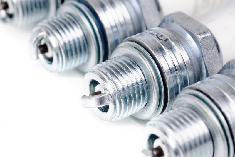
 Here are few such famous car part brands (in no particular order) for your consideration: